Mfr Part # MB10S
BRIDGE RECT 1P 1KV 500MA 4-SOIC
onsemi
License: See Original Project
Courtesy of All About Circuits
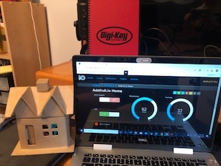
Everything these days is becoming connected to the internet creating the internet of things. In this teardown, we’ll look at a Hive LED bulb with Wi-Fi capabilities to see how it works.
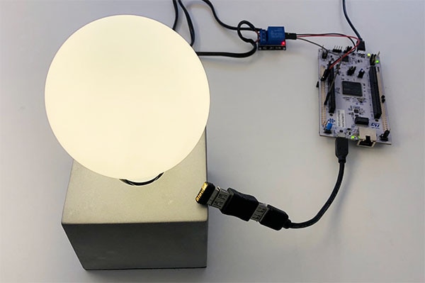
The Bulb
The Hive bulb shown in this teardown is an Edison screw type commonly found in house electrical systems. The Edison screw bulb has some advantages over other bulb fittings with one major feature being that the screw itself is connected to neutral. This means that the fitting that houses the bulb will not (or should not) shock a person if they make contact with the threaded hole. For someone to get an electric shock, they would have to reach right to the bottom where the live contact is found.
Electrical information found on the bulb
Obtaining access to the internal electronics was first attempted by removing the Edison cap using a small screwdriver. However, while the electronics could be seen, they could not be removed. Having taken apart something similar in the past, the top of the bulb (made of plastic and not glass) was sawed off to reveal the LED lighting PCB. From there, two small screws can be found which when unscrewed allow the PCB to slide out from the top.
Removing the Edison cap
The LED PCB and two screws
Interestingly, the bulb has a metal shield surrounding the PCB space. Considering how a Wi-Fi antenna sticks out of a small slit where the LEDs are located the metal shielding must be for EMC reasons. Most Wi-Fi related products on the market contain some form of electromagnetic shielding as to comply with rules and regulations found in the FCC (US) and CE directives (Europe).
Metal shielding inside the bulb structure
The PCB
The main PCB shows an interesting design with the LED PCB being connected to the main PCB at 90 degrees using a 3-pin header connector. Some of the components that can be seen on the top side include a transformer, several capacitors of different types (electrolytic, polyester etc), surface components, and inductors. The top side of the PCB also shows a Wi-Fi module that is connected to the main PCB via a slot that contains solder contacts.
The main PCB
The back of the LED PCB is of particular interest due to the use of a thick metal shield that sits on the back. This shield is in place to prevent stray electromagnetic waves from leaving the bulb and interfering with nearby electronics (The same reason the case of the bulb is lined with metal).
The PCB alongside the LED panel with metal plating
Second view of the PCB showing the Wi-Fi modules antenna sticking out
The Wi-Fi module and some surface mount parts on the topside of the PCB
The underside of the PCB reveals many surface mount components including a rectifier (ON Semiconductor’s MB10S), several unidentifiable ICs (3C2DN and TXD17), and plenty of passive components. The slot for the Wi-Fi module can also be found with solder contacts.
The underside of the PCB
Wi-Fi module removed from main PCB
Wi-Fi Module
The Wi-Fi module on the Hive Bulb is based around NXP’s JN5169 wireless microcontroller. This microcontroller, a 32-bit RSIC CPU, features 512kB of embedded flash, 4kB of EEPROM, 32kB RAM, SPI, ADC, I2C, and many other peripherals. The controller is also suitable for applications involving ZigBee, compliant with 2.4 GHz IEEE802.15.4, and can allow for OTA updating (over the air).
The Wi-Fi Module
The Wi-Fi module itself has a very useful feature on the component legend where each IO gold pad is labelled with its function (these labels include VDD, RX, TX, MISO and GND). The Wi-Fi module has many stitching via around the floodplains which are used to help mitigate against EM emissions whereas the antenna (the thin PCB stick) has no plains at all nearby (plains would absorb the Wi-Fi signals).
PCB underside showing labels and pins
The Wi-Fi Module showing the IC and top side labels
Summary
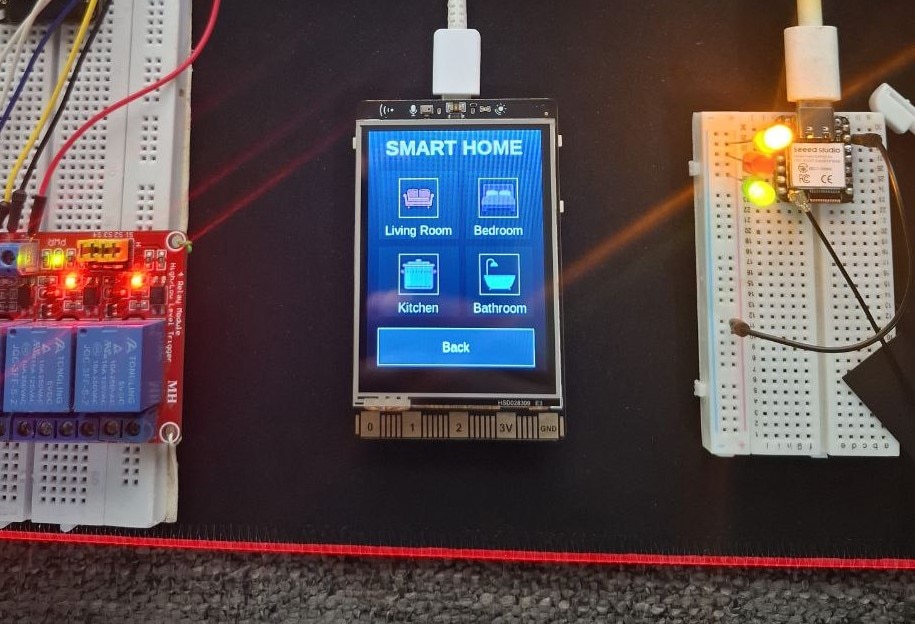
The Hive Bulb demonstrates how few components are needed to get any device connected to the internet in some fashion. With Wi-Fi modules and Wi-Fi SoCs becoming simpler and cheaper, there are almost no hurdles that can prevent a Wi-Fi enabled device from being designed.
Schematic