RP2350-LCD Weather Station With Color Warning Alerts
2025-12-10 | By Ron Cutts
License: GNU Lesser General Public License Ambient Displays Humidity Temperature Arduino
Create a simple and beginner-friendly weather station using the RP2350-LCD 📟 and DHT11 🌡️ sensor in Visuino. The temperature and humidity values are shown on the LCD with color-coded warning indicators 🔴🟢🔵.
Temperature displays green 🟢 when within range and red 🔴 when outside, while humidity shows blue 🔵 within range and red 🔴 for warnings.
All limits can be easily adjusted inside the Visuino project ⚙️.
If you want to explore the project further, here’s an idea for an upgrade 💡:
Add an optional piezo buzzer alarm 🔔 that activates when the temperature or humidity goes out of the safe range. A great starting project for beginners learning Visuino, sensors, and the RP2350 platform
Step 1: What You Will Need
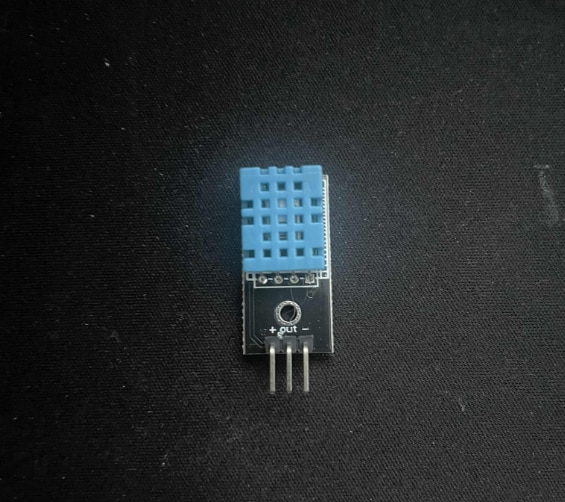
RP2350-LCD-0.96
Breadboard (Optionally)
Visuino program: Download Visuino
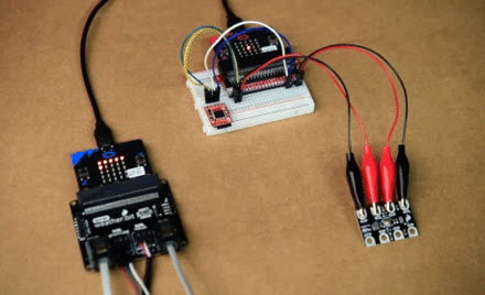
Step 2: The Circuit
Connect RP2350-LCD-0.96 pin VBUS to DHT11 pin (VCC +)
Connect RP2350-LCD-0.96 pin GND to DHT11 pin (GND -)
Connect RP2350-LCD-0.96 pin GP2 to DHT11 pin (OUT)
Step 3: Start Visuino, and Select the Board Type
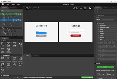
Start Visuino as shown in the first picture. Click on the "Tools" button on the Arduino component (Picture 1) in Visuino. When the dialog appears, select "Waveshare RP2350 + LCD Display 0.96" as shown in Picture 2
Step 4: In Visuino, Add Components


Add "Humidity and Thermometer DHT11/21/22/AM2301" component
Add 2X "Compare Analog Range" component
Add 2X "Digital To Color" component
Step 5: In Visuino, Set LCD


Select Waveshare RP2350 + LCD Display 0.96" and in the editor
Modules>Display>Orientation set to goLeft
Modules>Display>Elements, click on the [...] button, so that the "Elements" window will open.
In the Elements Dialog, drag "Draw Text" from the right side to the left and in the properties window set "Fill Color" to aclBlack, "Text" to TEMP, and "Y" to 5
In the Elements Dialog, drag "Text Field" from the right side to the left side to the left and in the properties window, set "Size" to 2, "Y" to 20, select "Color", and click on the pin Icon, select "Alpha Color SinkPin", set "Color" to aclGreenYellow
In the Elements Dialog, drag another "Draw Text" from the right side to the left and in the properties window set "Fill Color" to aclBlack, "Text" to HUM, and "Y" to 45
In the Elements Dialog, drag another "Text Field" from the right side to the left side to the left and in the properties window, set "Size" to 2, "Y" to 60, select "Color", and click on the pin Icon, select "Alpha Color SinkPin", and set "Color" to aclAqua
In the Elements Dialog, drag another "Draw Bitmap" from the right side to the left side to the left and in the properties window, set "X" to 90 and "Y" to 5, select "Bitmap", and click on the 3 dots button, and in the "Bitmap editor", load the bitmap that you attached here.
Close all the Dialogs
Step 6: In Visuino Set Components


Select "CompareRange1" and in the properties window set "Is Outside Range" to True, "Range" > "Max" to 27, and "Range" > "Min" to 10
This means that if the Temperature is below 10 or above 27, the output of the component will be True
Select "CompareRange2" and in the properties window set "Is Outside Range" to True, "Range" > "Max" to 60, and "Range" > "Min" to 50
This means that if the Humidity is below 50 or above 60, the output of the component will be True
Select "DigitalToColor1" and in the properties window set "False Value" to clLime and "True Value" to clRed
This means that if the output from the "CompareRange1" is True, the color will be set to red; if not, the color will be Lime
Select "DigitalToColor2" and in the properties window set "False Value" to clAqua and "True Value" to clRed
This means that if the output from the "CompareRange2" is True, the color will be set to red; if not, the color will be Blue
Step 7: In Visuino Connect Components
Connect "HumidityThermometer1" pin [Sensor] to "RP2350 + LCD Display 0.96" Digital pin [2]
Connect "HumidityThermometer1" pin [Temperature] to "Text Field1" pin [In]
Connect "HumidityThermometer1" pin [Temperature] to "CompareRange1" pin [In]
Connect "HumidityThermometer1" pin [Humidity] to "Text Field2" pin [In]
Connect "HumidityThermometer1" pin [Humidity] to "CompareRange2" pin [In]
Connect "CompareRange1" pin [Out] to "DigitalToColor1" pin [In]
Connect "CompareRange2" pin [Out] to "DigitalToColor2" pin [In]
Connect "DigitalToColor1" pin [Out] to "Text Field1" pin [Color]
Connect "DigitalToColor2" pin [Out] to "Text Field2" pin [Color]
Step 8: Generate, Compile, and Upload the Code

In Visuino, at the bottom, click on the "Build" tab, make sure the correct port is selected, then click on the "Compile/Build and Upload" button.
Step 9: Play
Congratulations! You have completed your weather station project with Visuino. Also attached is the Visuino project that I created for this. You can download and open it in Visuino: https://www.visuino.com
Download Visuino file: RP2350-LCD-weather.visuino