Mfr Part # A000073
ARDUINO UNO SMD R3 ATMEGA328
Arduino
License: General Public License Infrared (IR) RFID / NFC Wireless Arduino
An accessible yet powerful embedded project for automated vehicle detection, RFID payment processing, and gate actuation
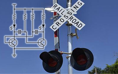
Automating everyday infrastructure not only accelerates systems but also lays the foundation for smarter cities and transportation networks. An Arduino-based Automatic Toll Gate System employs affordable hardware to simulate an electronic toll collection (ETC) system that detects vehicles, verifies digital payment credentials, and actuates a barrier — all without human intervention. This project is ideal for electronics hobbyists, students, and professionals exploring embedded systems, sensor integration, and control logic.
At its core, this system replaces traditional toll booths and manual cash handling with contactless detection and control. Vehicles approaching the toll point are sensed using infrared (IR) obstacle detectors. A mounted RFID card reader then authenticates a digital token associated with the vehicle. If the account balance on the RFID tag is sufficient, a toll amount is deducted, and a servo motor swings open the gate barrier. After the vehicle clears the exit sensor, the gate closes, and the system resets for the next transaction.
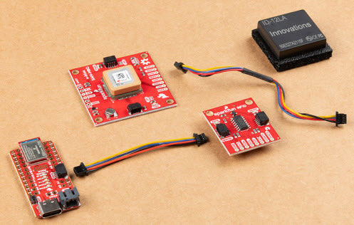
To build this Automatic Toll Gate System Project Using Arduino, you will need:
Arduino Uno – Serves as the main microcontroller to process sensor data, execute logic, and switch outputs.
RFID RC522 Reader & Cards/Tags – Operates at 13.56 MHz; reads unique IDs to simulate account credentials.
Infrared (IR) Sensors – Two units detect vehicle presence at entry and after the gate.
Servo Motor (e.g., SG90 / MG996R) – Controls the physical barrier; requires PWM control from the Arduino.
LED Indicators (Red/Green) – Provide visual status feedback for access denied vs. granted.
Power & Wiring – 5 V supply for Arduino and peripherals, plus jumper wires and breadboard for prototyping.
These components strike a balance between cost, simplicity, and expandability, making the setup approachable for beginners while still extendable with advanced features like displays or connectivity modules.
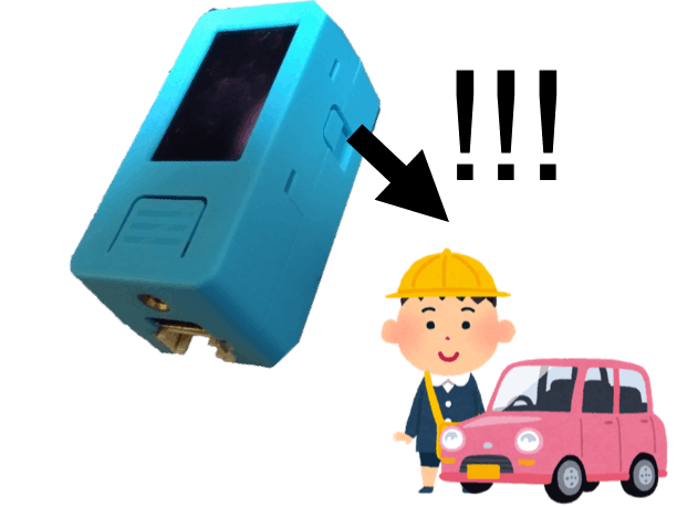
As a vehicle nears the toll gate, the first IR sensor triggers, signaling the Arduino to initiate RFID scanning.
The RFID reader polls for a tag. Once detected, the system retrieves its UID and compares it against stored account records in firmware.
If the card is recognized and the associated balance meets or exceeds the preset toll cost, the system:
Deducts the toll from the balance.
Illuminates the green LED to indicate authorization.
Commands the servo to open the gate barrier.
If the tag is unknown or has insufficient balance, the red LED is activated and the gate remains closed.
Once the vehicle crosses the threshold and triggers the second IR sensor, the Arduino signals the servo to close the gate and returns the system to idle.
This closed-loop flow ensures that every vehicle is tracked from approach to departure, with clear visual feedback at each decision point.
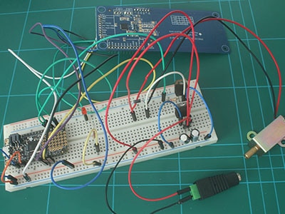
All components connect to the Arduino’s digital and PWM pins. Best practices suggest powering the RFID module at 3.3 V as required, while other modules like sensors and LEDs run from the Arduino’s 5 V rail. Use common ground throughout to prevent erratic behavior.
A typical wiring approach:
RFID Module: SPI pins (SDA, SCK, MOSI, MISO) to digital I/O on the Arduino.
IR Sensors: Digital input pins.
Servo Motor: PWM-capable output pin.
LEDs: Digital output pins with current-limiting resistors.
Use a breadboard-first approach for prototyping before committing to a custom PCB for enhanced robustness.
The Arduino sketch systematically:
Initializes SPI and RFID libraries.
Sets gate servo to a default closed position.
Polls IR sensors and RFID tags inside the main loop.
Executes balance logic and triggers actuators accordingly.
Structured code improves both readability and maintainability — crucial for future upgrades like database connectivity, display outputs, or cloud logging.
Beyond educational value, the core concepts in this project mirror real ETC systems used globally:
Highway toll plazas accelerate throughput and reduce congestion.
Commercial parking facilities employ similar RFID/automation for access control.
Gated communities and campuses use RFID detection for vehicle identification and entry management.
Integrations like LCDs, IoT connectivity, and backend logging systems can elevate this from a prototype into scalable infrastructure.
Common challenges include:
No RFID detection: Check for proper 3.3 V supply and secure SPI wiring.
Servo jitter or no movement: Ensure ample power and correct PWM pin assignment.
False IR triggers: Adjust sensor positioning and noise filtering in code.
This foundational project can evolve with more sophisticated features:
LCD or OLED Display to show balance and status.
Wi-Fi or GSM Modules for cloud-based toll logging.
Mobile Apps for user account management.
OCR Cameras for plate recognition linked to dynamic billing.
These expansions align with smart infrastructure trends and add real engineering value.